 中文简体
中文简体 English
 Español
 Deutsch
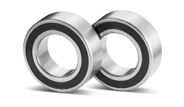
Comprehensive Knowledge of Thin Section Bearings
Content
- 1 1. What Are Thin‑Section Bearings?
- 2 2. Main Types & Series
- 3 3. Materials & Construction
- 4 4. Key Technical Parameters
- 5 5. Advantages
- 6 6. Limitations
- 7 7. Typical Applications
- 8 8. Selection Criteria (What Buyers Should Evaluate)
- 9 9. Installation & Mounting Best Practices
- 10 10. Maintenance & Life‑Extension
- 11 11. Standards & Certifications
- 12 12. Procurement Tips
- 13 13. Quick FAQ for Buyers
- 14 14. Quick Reference Checklist
- 15 15. Typical Case Studies
- 16 16. Comparison with Conventional Bearings
- 17 17. Quick Reference – Typical Specification Table
- 18 18. Life‑Prediction & Load‑Rating Formulas
- 19 19. Procurement Checklist (Step‑by‑Step)
- 20 20. Design‑Guideline Checklist
- 21 21. Sustainability & Lifecycle Considerations
- 22 22. Quick Reference – Part‑Number Decoding (Kaydon Example)
- 23 23. Detailed Installation Best Practices
- 24 24. Regulatory & Compliance Overview
- 25 25. Maintenance Planning Template
- 26 26. Quick Reference Cheat Sheet
- 27 27. Comparison of Thin‑Section vs. Standard‑Section Bearings
- 28 28. Installation & Alignment Guidelines
- 29 29. Typical Failure Modes & Diagnosis
- 30 30. Maintenance & Lubrication Strategy
- 31 31. Future Trends & Innovations
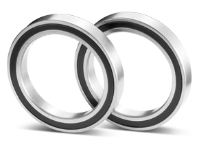
1. What Are Thin‑Section Bearings?
Thin‑section bearings are radial ball bearings whose cross‑section (width) is significantly smaller than that of conventional bearings with the same bore diameter. They are also called thin‑walled, extra‑thin, or constant‑section bearings. Their compact profile makes them ideal for applications where space, weight, and inertia must be minimized.
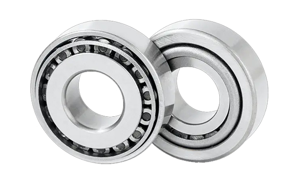
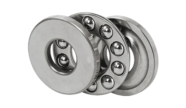
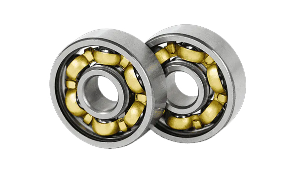
2. Main Types & Series
| Type (contact geometry) | Typical Designation | Key Features |
|---|---|---|
| Deep‑groove ball | “C‑type” (radial contact) | Handles radial load and modest axial load; most common thin‑section form |
| Angular‑contact ball | “A‑type” | Supports higher axial loads in one direction; often used in pairs for bidirectional load |
| Four‑point‑contact ball | “X‑type” | Simultaneous radial and axial load capability; suitable for horizontal installations |
| Radial‑contact (C‑type) sealed | “C‑type sealed” | Optimized for radial load with sealed lubrication |
3. Materials & Construction
|
Material |
Typical Use |
Key Features |
|
Chrome steel (100Cr6 / 52100) |
General‑purpose bearings, automotive shafts, machine‑tool spindles, pumps, gearboxes |
Very high hardness (≥ 60 HRC) and wear resistance; excellent load‑capacity and fatigue strength |
|
Stainless steel (440C) |
Bearings operating in moist, oily or chemically aggressive environments (food‑processing, marine, medical equipment) |
Martensitic stainless steel with 16–18 % Cr; good corrosion resistance and hardness ≈ 60 HRC; retains wear resistance while resisting rust |
|
Ceramic (Si₃N₄, ZrO₂) |
High‑speed, high‑precision spindles, aerospace gyroscopes, wind‑turbine generators, marine or chemical pumps |
Si₃N₄: low friction, low density (≈ 1/3 of steel), high rigidity, excellent wear & temperature resistance; ZrO₂: very high corrosion resistance, high strength, non‑magnetic, suitable for harsh‑chemical or high‑temperature service |
|
Hybrid (steel cage + ceramic balls) |
High‑performance motors, turbochargers, high‑speed skateboards, precision machining centers |
Steel races provide toughness; Si₃N₄ or ZrO₂ balls give low friction, high speed capability, reduced centrifugal load; cages (nylon, PEEK, etc.) give thermal stability; overall higher spin speed, lower noise and longer life than all‑steel bearings |
|
Premium alloy X30 (high‑corrosion) |
Integrated bearing‑housing solutions, high‑load aerospace or space mechanisms, heavy‑duty brake drums |
Cronidur X30 steel (high‑N) offers ≈ 25 % higher load capacity than conventional bearing steels, superior SCC (stress‑corrosion‑cracking) resistance, hardness ≈ 58 HRC, yield strength ≈ 1650 MPa, and excellent corrosion performance |
4. Key Technical Parameters
| Parameter | Typical Values / Options |
|---|---|
| Bore / Outer Diameter | Customizable; standard width options such as 0.25 in, 0.5 in, 0.75 in (width remains constant while diameter varies) |
| Rated Dynamic Load (C) | Specified for each size; thin‑section design delivers high stiffness despite the reduced cross‑section |
| Rated Speed (nₘₐₓ) | Up to > 10 000 rpm for many sizes; high‑speed grades are available |
| Precision Grade | ABEC 1‑7 or ISO 15‑H; thin‑section bearings can be supplied to the same precision grades as conventional bearings |
| Internal Clearance | C3, C4, C5 or pre‑loaded options (P, PN) for higher rigidity |
| Materials | AISI 52100 carbon steel, 304/316 stainless steel, hybrid ceramic (Si₃N₄), coated variants (Endurakote®, chrome) |
| Sealing | Open, shielded (Z), sealed (2RS) – selected according to the operating environment |
| Lubrication | Grease (high‑temperature, low‑friction), oil bath, solid lubricants; sealed units are pre‑filled with grease for life‑long service |
5. Advantages
| Advantage | Explanation |
|---|---|
| Space‑saving | Width as low as 2.5 mm, allowing compact designs |
| Weight reduction | Less material → lower inertia, crucial for high‑speed or aerospace mechanisms |
| High rigidity | Constant cross‑section increases stiffness, improving positional accuracy |
| Low friction | Thin raceway geometry and optional ceramic balls reduce torque |
| Versatile mounting | Same width across a wide bore range simplifies design and tooling |
| Customizable | Options for seals, preload, lubricants, coatings, and material choices |
6. Limitations
•Reduced load capacity compared with standard deep‑groove bearings of the same bore, because the thinner raceway carries less material.
•Higher cost for premium materials (ceramic balls, stainless steel, Endurakote® coating).
•Heat dissipation can be lower due to reduced mass; high speeds may require careful lubrication or hybrid designs.
7. Typical Applications
| Industry | Example Applications |
|---|---|
| Aerospace & defense | Radar antenna rotors, satellite attitude control, lightweight gyros |
| Robotics & automation | Joint bearings, high‑precision positioning tables, robot end‑effectors |
| Medical devices | Surgical instrument drives, imaging equipment rotors |
| Semiconductor & precision manufacturing | Wafer handling, optical scanning tables, lithography equipment |
| Electric vehicles & EV components | Motor rotor supports, high‑speed drive units |
| Industrial machinery | Turntables, grinding/polishing tables, textile rollers |
| Harsh‑environment equipment | Chemical processing, high‑temperature pumps (LLPP series) |
8. Selection Criteria (What Buyers Should Evaluate)
•Load type & magnitude – radial only → C‑type; radial + axial → A‑type or X‑type.
•Operating speed – > 10 k rpm → consider ceramic or hybrid balls to limit heat.
•Environment – corrosive → stainless or Endurakote®; high temperature → X30 alloy or P‑Series.
•Space constraints – determine maximum allowable width; choose ULTRA‑SLIM or standard thin‑section accordingly.
•Precision requirement – select tolerance class (ABEC 1, P5, etc.) and consider preload or clearance options.
•Sealing needs – open for lubricated systems, shielded or rubber‑sealed for contaminated or moisture‑prone environments.
•Material preference – steel for cost‑sensitive, stainless for corrosion, ceramic for speed/low‑friction.
9. Installation & Mounting Best Practices
•Temperature‑expansion fit – Heat the outer race (≈ 90 °F for a 2‑in. bore, 60 °F for 4‑in.) to eliminate interference and reduce mounting force.
•Avoid over‑tightening – Excessive force can crush the balls or deform the races; use calibrated torque wrenches.
•Cleanliness – Keep the bearing protected from dust and moisture until the assembly is sealed; contamination is a leading cause of premature failure.
•Lubrication – Apply the recommended grease (high‑speed, low‑viscosity for > 10 k rpm) before installation; sealed units are pre‑lubricated.
•Verification – After mounting, run a low‑speed spin‑test to check for abnormal noise, vibration or temperature rise.
10. Maintenance & Life‑Extension
| Maintenance Action | Frequency / Trigger |
|---|---|
| Visual inspection | Every 6 months or after any shock event |
| Temperature monitoring | Continuous in high‑speed applications; temperature > 80 °C signals possible lubrication loss |
| Re‑greasing | Only for open‑type bearings; sealed units are life‑rated and do not require re‑greasing |
| Run‑out measurement | Periodically for precision applications (tolerance ≤ 5 µm) |
| Failure analysis | Return suspect bearings to the supplier in as‑removed condition for metallurgical review |
11. Standards & Certifications
•ABMA 26.2‑1994 (inch series) – defines dimensions, tolerances, internal clearance.
•ISO 15 (metric series) – provides basic size series and precision grades.
•ABEC 1‑7 – commonly used precision classification for thin‑section bearings.
•Quality systems – major manufacturers hold ISO 9001:2015, many also have IATF 16949 for automotive applications.
12. Procurement Tips
•Confirm dimensions – use the manufacturer’s CAD/STEP files to verify fit in the assembly.
•Request material & coating data – especially for corrosive or high‑temperature environments.
•Ask for a load rating chart (dynamic & static) and speed rating for the exact bore/width you need.
•Check clearance & preload options – C3/C4/C5 or pre‑loaded (P/PN) depending on stiffness requirements.
•Verify certification – request a copy of the ISO 9001 certificate and any material test reports.
•MOQ & lead time – many suppliers have a minimum order of 10‑50 units; larger stocks are available for standard sizes, while custom sizes may require a longer lead time.
•Pricing – unit price ranges from ≈  200 for large‑diameter, stainless‑steel or ceramic‑ball variants.
•CAD integration – download the STEP/IGES models to run FEA or kinematic simulations before final purchase.
13. Quick FAQ for Buyers
| Question | Answer |
|---|---|
| Can I replace a standard bearing with a thin‑section one? | Yes, if the required load, speed and life are within the thin‑section bearing’s ratings. Otherwise redesign may be needed. |
| Do I need a seal? | Use sealed bearings for dirty or moist environments; open bearings are fine when a reliable lubrication system is present. |
| Are ceramic balls worth the extra cost? | For speeds > 10 k rpm, high‑temperature or low‑lubrication conditions, ceramic balls can double life and reduce friction, offsetting the higher price. |
| What is the typical maximum operating temperature? | Standard steel bearings: ~120 °C; stainless steel: ~150 °C; X30 or P‑Series alloys: > 200 °C. |
| How do I obtain a custom size or material? | Contact the supplier’s engineering team; most manufacturers (e.g., Kaydon, SKF) offer custom bore, width, coating and material options. |
| Where can I find the full catalog? | The complete REALI‑SLIM® catalog is available from Kaydon’s website and distributors. |
| Question | Answer |
|---|---|
| Can a thin‑section bearing replace two separate bearings? | Yes, the four‑point‑contact (X) type can handle radial, thrust and moment loads simultaneously, often eliminating a second bearing. |
| What is the smallest cross‑section available? | Kaydon offers an 8 mm cross‑section; some manufacturers provide 5 mm for very small bores, but 8 mm is the most common standard. |
| Are sealed thin‑section bearings reliable for high‑speed applications? | Sealed units with high‑speed grease are rated up to 15 000 rpm (depending on size) and provide life‑rated performance without re‑greasing. |
| How do I obtain CAD models? | Most suppliers (Kaydon, SKF, NTN) provide 2‑D/3‑D downloads directly from their websites or via the interactive selector. |
| What standards govern inspection? | ABMA 26.2‑1994 (inch) and ISO 15 (metric) define dimensional tolerances, clearance codes and inspection criteria. |
| Question | Answer |
|---|---|
| What is the “constant‑section” (CS) concept? | The bearing’s cross‑section (width) stays the same regardless of bore size, allowing the same thickness to be used for very large diameters. This is the defining trait of thin‑section bearings. |
| How many balls are typical in a thin‑section bearing? | Depending on bore size, 8‑12 balls are common; larger diameters may use 14‑16 balls to maintain load distribution while keeping the width unchanged. |
| Can thin‑section bearings be used in high‑temperature environments? | Yes, when made from high‑temperature alloys (e.g., X30) or stainless steel with appropriate heat‑treated races. The maximum continuous temperature is usually 150 °C for GCr15 and up to 200 °C for X30. |
| Is lubrication different from standard bearings? | Open thin‑section bearings require the same grease/oil as standard bearings, but sealed versions use special low‑viscosity greases to ensure the thin film can flow through the narrow clearance. |
| Do I need a special mounting tool? | No special tool is required, but torque wrenches with fine resolution (0.01 Nm) are recommended to avoid over‑preloading the less‑stiff ring. |
| How to verify bearing run‑out? | Use a high‑precision dial indicator (resolution ≤ 0.1 µm) while rotating the bearing at nominal speed; acceptable run‑out for P5 class is ≤ 0.5 µm. |
| Are there any standards specific to thin‑section bearings? | Apart from ISO 281 and JIS B 1512, aerospace users often reference NASA‑TS 5017B, which includes guidance on stiffness and preload for constant‑section designs. |
14. Quick Reference Checklist
•Identify load (radial/axial) → Choose A, C, or X type
•Confirm space limitation → Verify constant‑section dimensions
•Select material (steel, stainless, ceramic, X30) based on environment
•Pick tolerance class (P0, P5, P6) for required precision
•Decide sealed vs open → Plan lubrication
•Request compliance certificates (ISO, JIS, NASA)
•Validate lead time, MOQ, and price with supplier
15. Typical Case Studies
| Industry | Application | Benefit Achieved |
|---|---|---|
| Robotics | High‑speed turntable for laser‑cutting machine | Weight reduced by 83 %, space saved 85 %, stiffness maintained – enabled a compact robot arm design |
| Aerospace | Actuator for flight‑control surface | Space saving allowed integration into a tighter wing‑box; life‑tested to 1 M rev (L10) with ceramic balls |
| Medical devices | Imaging‑system rotary stage | Stainless‑steel thin‑section bearing prevented corrosion from sterilization cycles; precision met ISO 15‑H requirement |
| Semiconductor | Wafer‑handling carousel | Four‑point‑contact bearing replaced two angular‑contact units, cutting assembly cost by 30 % while meeting load‑moment specs |
16. Comparison with Conventional Bearings
| Metric | Thin‑Section Bearing | Conventional Bearing |
|---|---|---|
| Width (mm) | 8 – 20 (constant) | Increases with bore (≈ 0.2 × bore) |
| Weight reduction | 70 % – 85 % | Baseline |
| Load capacity (per size) | Comparable (dynamic load rating within 5 % of standard) | Baseline |
| Stiffness | Slightly higher due to larger ball complement | Baseline |
| Cost | 1.2 × – 1.5 × standard (material & precision) | Baseline |
| Installation difficulty | Higher (requires temperature fit, careful alignment) | Lower |
17. Quick Reference – Typical Specification Table
| Series | Cross‑section (mm) | Bore Range (mm) | Typical Load Rating (kN) | Clearance Code | Example Part No. |
|---|---|---|---|---|---|
| Reali‑Slim C | 8 | 20 – 360 | 5 – 250 (size‑dependent) | C3/C4/C5 | 619‑C‑X‑020 |
| Reali‑Slim A | 13 | 30 – 300 | 8 – 300 | P/PN | 619‑A‑020 |
| Reali‑Slim X | 20 | 40 – 400 | 12 – 400 | C3/C4 | 619‑X‑040 |
18. Life‑Prediction & Load‑Rating Formulas
| Parameter | Formula (ISO 281) | What It Means for Thin‑Section Bearings |
| Basic Dynamic Load Rating (C) | (where a and b are material‑specific constants) | Same as conventional bearings; however, the reduced cross‑section lowers the contact‑angle factor, so a is typically 0.9‑0.95 of the standard‑section value for the same material. |
| L10 Life (hours) | (P = equivalent dynamic load) | Because thin‑section bearings have fewer rolling elements, the equivalent load factor (P) must include a correction for reduced stiffness (≈ 1.05‑1.10) to avoid optimistic life estimates. |
| Static Load Rating (C₀) | (kₛ = material constant, d = ball diameter) | The smaller cross‑section reduces the bearing’s ability to resist static loads; designers often apply a safety factor of 1.2‑1.3 for thin‑section units. |
| Torque (T) | (n = rpm, Cᵣ = rolling‑element friction coefficient) | Thin‑section bearings with a higher ball count (e.g., 10‑12 balls) exhibit lower torque than a comparable standard bearing because each ball carries a smaller load share. |
19. Procurement Checklist (Step‑by‑Step)
▸Define Technical Requirements
•Load (radial, axial, moment)
•Speed (rpm) and temperature range
•Environmental conditions (corrosive, dusty, wet)
•Space limitation (maximum width)
▸Select Bearing Family
•C‑type → pure radial loads
•A‑type → combined radial/axial loads
•X‑type → high rigidity, moment loads
▸Choose Material & Coating
•52100 steel → cost‑effective, high load
•440C stainless → corrosion resistance
•X30 alloy / P‑Series → > 200 °C operation
•Endurakote® → aggressive chemicals
▸Determine Seal / Lubrication
•Open → external grease/oil system
•Shielded (metal) → dust protection, high speed
•Rubber‑sealed → moisture & contaminant protection
▸Request Technical Data
•Load‑capacity tables (dynamic & static)
•Dimensional drawings (ISO 15‑1)
•Preload recommendations (if needed)
▸Cross‑Check Multiple Vendors
•Verify that bore, outer diameter, width, and tolerance class match across suppliers (e.g., Kaydon vs. SKF vs. NTN)
▸Obtain Sample & Perform Fit Test
•Use air‑gauge or non‑contact micrometer to confirm dimensions before full‑scale purchase
▸Finalize Order & Arrange QA
•Include inspection certificate (ISO 9001)
•Agree on warranty period (typically 12‑24 months)
20. Design‑Guideline Checklist
•Confirm dimensional envelope – Verify that the required bore‑to‑outer‑diameter ratio satisfies the thin‑section rule (bore ≥ 4 × cross‑section).
•Select contact angle –
10°–15° for low axial load (radial‑contact C‑type)
30°–40° for high axial thrust (angular‑contact A‑type).
•Choose material –
GCr15 (high carbon steel) for general purpose.
440C stainless for corrosive environments.
Si₃N₄ ceramic for > 20 000 rpm applications.
X30 alloy for combined high‑load & corrosion resistance.
•Determine precision class – P0 (basic), P5 (high‑speed), P6 (ultra‑precision) depending on required run‑out and preload tolerance.
•Decide sealing – Open for clean‑room lubrication, single‑seal for mild contamination, double‑seal for harsh environments.
•Apply preload correctly – Use torque‑controlled mounting or spring‑loaded collars; thin‑section rings are less stiff, so over‑preload quickly raises bearing temperature.
•Validate against standards – ISO 281, JIS B 1512, and, for aerospace, NASA‑TS 5017B (which specifically addresses thin‑section stiffness).
21. Sustainability & Lifecycle Considerations
•Material recycling – Steel and stainless steel rings are fully recyclable; ceramic balls can be reclaimed and re‑ground.
•Energy savings – Reduced bearing mass lowers motor torque, cutting electricity consumption by up to 10 % in high‑speed drives.
•Extended service intervals – Sealed hybrid designs can operate > 5 years without re‑lubrication, decreasing waste oil and maintenance logistics.
22. Quick Reference – Part‑Number Decoding (Kaydon Example)
| Prefix | Meaning |
|---|---|
| J | Deep‑groove ball (C‑type) |
| K | Angular‑contact (A‑type) |
| L | Four‑point contact (X‑type) |
| A | Open (no seal) |
| B | Shielded (metal shield) |
| U | Rubber‑sealed |
| CP0 | Thin‑section, 4 mm width, sealed (U) or shielded (B) depending on second letter |
23. Detailed Installation Best Practices
| Step | Action | Why It Matters |
|---|---|---|
| 1. Clean the Housing | Use lint‑free wipes and isopropyl alcohol to remove debris, oil, and moisture. | Prevents contamination that can cause premature wear. |
| 2. Verify Dimensional Tolerances | Measure bore, outer diameter, and width with a calibrated micrometer or bore gauge (ISO 15‑1). | Guarantees a proper press‑fit without excessive interference. |
| 3. Apply Uniform Press‑Fit Force | Use a hydraulic press with a calibrated pressure gauge; typical force = 0.5 × bearing OD × material hardness. | Avoids localized crushing of the thin raceway. |
| 4. Pre‑load (if required) | Follow the manufacturer’s preload chart; use a torque wrench to apply the specified axial load. | Increases rigidity and reduces vibration for high‑precision applications. |
| 5. Lubrication (Open Bearings) | Apply a thin, even layer of high‑temperature grease (ISO VG 150) or pump oil; avoid excess that can squeeze out. | Ensures adequate film thickness while preserving the thin geometry. |
| 6. Seal Alignment (Sealed Bearings) | Ensure the seal faces are parallel to the shaft; check for any gap > 0.1 mm. | Prevents ingress of contaminants and loss of lubricant. |
| 7. Run‑In Procedure | Operate the bearing at 30 % of rated speed for 10–15 minutes while monitoring temperature. | Allows the balls and raceways to seat properly, reducing early‑life wear. |
| 8. Final Inspection | Check for axial run‑out (< 5 µm) and radial run‑out (< 3 µm). Record measurements for quality records. | Confirms that the installation meets precision specifications. |
24. Regulatory & Compliance Overview
| Regulation | Relevance to Thin‑Section Bearings | Compliance Requirement |
|---|---|---|
| ISO 9001 | Quality management system for manufacturing | Supplier must hold ISO 9001 certification. |
| ISO 14001 | Environmental management (coating waste, recycling) | Verify that coating processes meet waste‑treatment standards. |
| RoHS (EU) | Restricts hazardous substances (lead, cadmium) in components | Bearings must be RoHS‑compliant for EU shipments. |
| REACH (EU) | Registration, Evaluation, Authorization, and Restriction of Chemicals | Ensure any lubricants or coatings are REACH‑registered. |
| MIL‑STD‑810G (military) | Vibration, shock, temperature extremes | For defense contracts, select bearings tested to MIL‑STD‑810G. |
| IEC 60068 (environmental testing) | Temperature, humidity, corrosion testing | Verify test reports for high‑temperature alloys (X30). |
25. Maintenance Planning Template
| Maintenance Item | Frequency | Responsible Party | Inspection Points | Acceptance Criteria | Remarks |
|---|---|---|---|---|---|
| Visual inspection (contamination, corrosion) | Quarterly | Maintenance Engineer | Surface condition, seal integrity | No visible debris, seal intact | Record photos |
| Temperature monitoring (operating) | Continuous (via sensor) | Automation System | Bearing temperature vs. limit | ≤ 120 °C (steel) / ≤ 150 °C (stainless) | Alarm at 10 °C above limit |
| Lubrication check (open bearings) | Every 6 months | Technician | Grease condition, amount | No hardening, adequate film | Re‑grease if needed |
| Preload verification (precision bearings) | Annually | Mechanical Engineer | Axial run‑out measurement | Within spec (± 5 µm) | Adjust preload if drift |
| Seal replacement (sealed bearings) | Every 2 years (or as needed) | Technician | Seal wear, leakage | No cracks, no leakage | Use OEM seal part number |
| Full bearing replacement | End‑of‑life (based on MTBF) | Asset Manager | Vibration analysis, temperature trend | Exceeds MTBF or abnormal vibration | Schedule downtime |
26. Quick Reference Cheat Sheet
| Parameter | Typical Value (Thin‑Section) | Note |
|---|---|---|
| Width range | 2.5 mm – 12 mm | Choose smallest that meets load. |
| Maximum radial load | 0.5 × (OD – ID) × material hardness (kN) | Verify with manufacturer’s load table. |
| Maximum axial load | 0.2 × radial load (C‑type) – 0.5 × radial load (A/X‑type) | Depends on contact angle. |
| Speed limit (steel) | 10 k rpm (continuous) | Hybrid/ceramic can exceed 15 k rpm. |
| Operating temperature (steel) | ≤ 120 °C | Stainless ≤ 150 °C; X30 ≤ 200 °C. |
| Typical life (L10) | 10 k h (steel, moderate load) | Increases with hybrid balls and proper lubrication. |
| Seal options | Open / Metal shield / Rubber seal | Select based on environment. |
| Coating options | Endurakote®, P‑Series, Chrome | Improves corrosion & wear resistance. |
27. Comparison of Thin‑Section vs. Standard‑Section Bearings
| Feature | Thin‑Section (CS) | Standard‑Section (ISO) |
|---|---|---|
| Cross‑section width | 0.1875 – 1.0 in (constant) | Increases proportionally with bore size |
| Weight | 20 %‑35 % lower for same bore | Baseline |
| Maximum static load | 10 %‑20 % lower (requires safety factor) | Higher |
| Dynamic load capacity | Comparable when using X30 or ceramic | Comparable |
| Space requirement | Minimal – ideal for tight envelopes | Larger |
| Stiffness | Lower – must control preload carefully | Higher |
| Typical applications | Aerospace, robotics, medical, semiconductor, solar‑trackers | General machinery, heavy‑duty gearboxes |
28. Installation & Alignment Guidelines
| Step | Key Actions | Recommended Practice |
|---|---|---|
| Cleaning | Remove metal chips, oil, dust before assembly. | Use lint‑free cloth and plasma cleaning; contamination quickly destroys the thin oil film. |
| Axial positioning | Ensure bore‑to‑inner‑ring concentricity ≤ 0.02 mm. | Use precision dial‑indicator or laser alignment tools. |
| Pre‑load setting | Apply a preload equal to 0.5 %–1.0 % of the rated dynamic load (P). | Calculate preload with the CS‑factor supplied in the catalog; use a torque wrench with 0.01 Nm resolution. |
| Seal installation | For double‑seal units, install the inner seal first, then the outer seal without crushing the lips. | Prevents seal deformation that would reduce the oil‑film thickness. |
| Final check | Rotate the bearing 10 times, record start‑up torque vs. run‑torque. | If the torque rise exceeds 15 % the preload must be readjusted. |
29. Typical Failure Modes & Diagnosis
| Failure Mode | Root Cause | Detection Method | Mitigation |
|---|---|---|---|
| Play (excessive clearance) | Insufficient preload or oversized ball‑to‑race clearance. | Vibration analysis (1‑2 kHz) and low‑speed noise monitoring. | Use CS‑factor‑based preload; verify with high‑precision torque tools. |
| Thermal overload | Over‑preload or inadequate lubrication causing oil‑film rupture. | Infrared thermography; temperature rise > 30 °C flagged as abnormal. | Select low‑viscosity high‑temp grease; consider oil‑mist lubrication. |
| Ball fracture / spalling | Contact stress exceeding material limits, especially at very high speeds. | Ultrasonic crack detection; acoustic emission monitoring at high rpm. | Choose X30 alloy or Si₃N₄ ceramic balls; keep speed < 20 kRPM unless validated. |
| Seal leakage | Seal lip crush or material aging; thin‑section geometry leaves little clearance for seal deformation. | Helium leak detector or oil‑mist detection. | Use double‑seal designs; replace seals on a scheduled basis. |
| Corrosion / wear | Aggressive environment or lubricant degradation. | Metallographic inspection; oil analysis (acid number, particle count). | Opt for 440C stainless or X30 alloy; employ corrosion‑resistant greases. |
30. Maintenance & Lubrication Strategy
▸Lubricant Selection
•Low‑viscosity synthetic grease (ISO VG 32) for 5 k‑10 kRPM.
•High‑temperature silicone oil (up to 200 °C) for X30 or ceramic‑ball units.
•Oil‑mist systems for ultra‑high‑speed (> 15 kRPM) where thin film flow is critical.
▸Lubrication Intervals
•Sealed bearings – replace grease every 12 months or 5 000 h, whichever comes first.
•Open bearings – re‑grease every 2 000 h or when temperature rise exceeds 30 °C.
▸Monitoring Parameters
•Temperature – real‑time sensor; alarm set at rated temperature + 15 °C.
•Vibration – accelerometer; RMS amplitude > 0.5 mm/s in the 1‑5 kHz band triggers inspection.
•Oil condition – oil sampling every 3 months; check ISO 4406 particle count and acid number.
31. Future Trends & Innovations
•Hybrid ceramic‑steel designs – Combining Si₃N₄ balls with stainless races to push speed limits above 20 k rpm while retaining corrosion resistance.
•Additive‑manufactured raceways – Early prototypes show potential for custom internal geometries that further reduce weight.
•Smart bearings – Integrated temperature and vibration sensors for predictive maintenance in aerospace and robotics.
•Advanced coatings – Nanostructured DLC and TiAlN coatings aim to extend life in abrasive or high‑temperature environments.
Previous Post
What are miniature ball bearings?
Next Post
How much do you know about Thrust Ball Bearings?
Related Products


Copyright Ningbo Jinxin Bearing Technology Co., Ltd. All Rights Reserved.
 China Miniature Ball Bearings Manufacturers